TetraAnt 15.5 GHz High Isolation
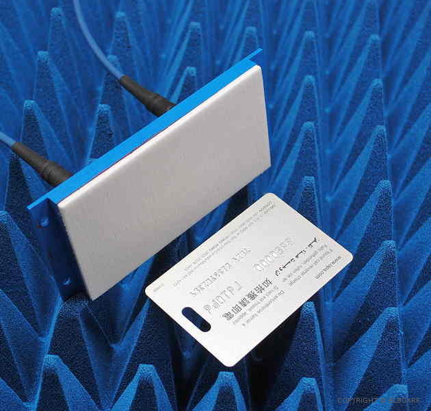
Ku-band dual radar antenna, High Isolation
- Frequency range Ku-band 15.4 - 16.1 GHz
- Two separate patch wideband antennas in a single case
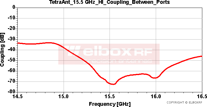
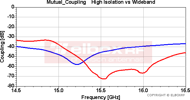
- Mutual coupling between antennas better than -60 dB; -70dB @ 15.5 GHz
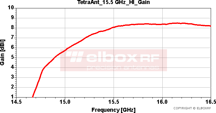
- Peak gain: 8 dBi
- HPBW: 81 x 60 deg @ 15.5 GHz
- Polarization: linear
- Polarization plane the same for both antennas
- Connector SMA(f) x 2, at the back
- Dimensions: 135 x 62 x 11 [mm] (without SMA connectors)
- Mass: 45 g
Important Feature:
- Small, extremely lightweight and durable
- Easy to integrate directly onto a transceiver PCB in a piggyback configuration
- Very low mutual coupling between antennas
- For professional application
The TetraAnt 15.5 GHz HI antenna was originally designed as the unmanned aerial vehicles (UAVs) noise radar antenna. The important feature is a small size compared to the credit card, a durable construction, low mass and a high isolation or a low mutual coupling - a key parameter for a radar antenna, where the transmit signal delivered to the Tx antenna should be suppressed as mach as possible in the Rx or receiving path.
In this antenna the transmit signal is attenuated by at least 60 dB in the Rx path.
This means that if the signal power delivered to one antenna is, for example, +30 dBm (1 W at 50 Ω), it will be attenuated by 60 dB at the output of the other antenna, resulting in a signal level of approximately -30 dBm in the receiving path.
This power level will be easily tolerated by the even low cost receiver amplifier IC, without causing saturation or other intermodulation effects in the receiving path.
The design process focused heavily on the small dimension, a low weight and a low mutual coupling between antennas resulted in good mentioned above parameters.
In a piggyback configuration, the antenna can be customised by removing the excess board. In this case the overall dimensions will be 115 x 62 x 11 mm
- Project - 2021. Designer: company owner-Przemyslaw Fert
TetraAnt 15.5 GHz HI Parameters
Electrical Parameters
- Frequency Range: 15.4 - 16.1 GHz
- Polarization: linear, the same polarization plane for both antennas
- Two antennas in the one case
- Impedance: 50 Ohm
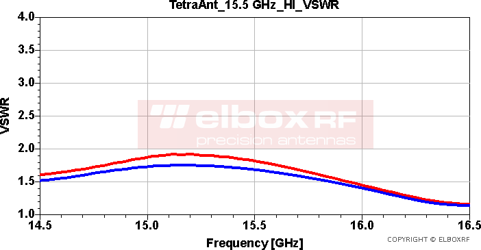
- VSWR: <=2.0
- Gain: 8 dBi
- Mutual Coupling <= -60 dB
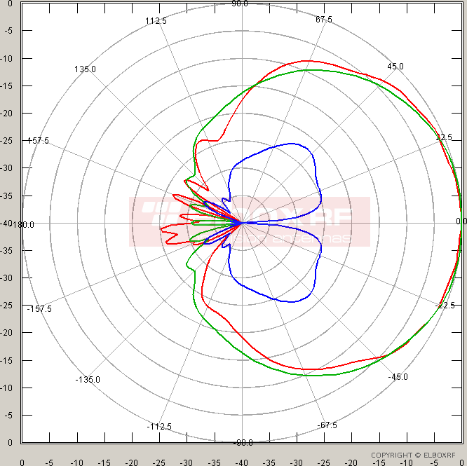
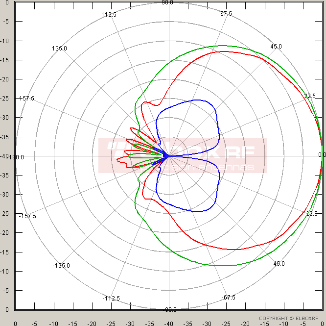
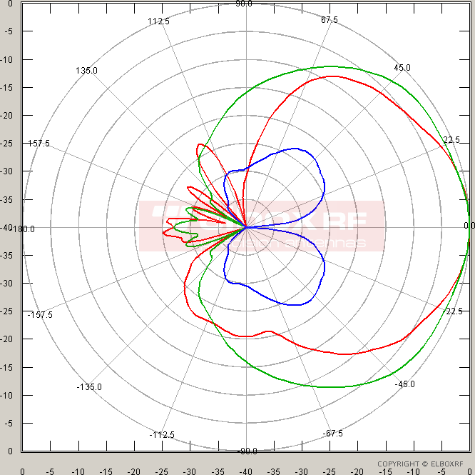
- Back Radiation: <= -25 dB, see radiation patterns
- X- (or cross-) polarization components: see radiation patterns
- E-plane and H-plane HPBW: see radiation patterns
- Maximum Power: 1 W
- Protection Against Static Electricity: NO
Mechanical Parameters
- Technology: Microstrip
- Connector: SMA Female at the back
- Dimensions: 135x62x18 mm, with the connector; 135 x 62 x 11 mm (without SMA connectors)
- Dielectric Radome: White Low-Loss Dielectric Material
- Construction: Completely weatherproof
- Operating Temperature Range: -30 to +50 C
- Mounting Kit: no
- Antenna's mass: 45 g
TetraAnt 15.5 GHz HI - VSWR
- Y axle starts at VSWR = 1.0
- Y division: 0.5
- X division: 100 MHz. The X full scale is 14.5 - 16.5 [GHz]
- Measurement-based data
TetraAnt 15.5 GHz HI - Coupling
- The coupling between ports of the antenna TetraAnt 15.5 GHz High Isolation version.
- For the frequency range 15.4 - 16.1 [GHz] the isolation is as high as >= 60 dB
- Measurement-based data
TetraAnt 15.5 GHz HI - Gain
- The antenna's gain was measured in the Far-Field range in a low scatter environment, with two-antenna method.
- This is realized gain measured on the antenna's connector. All losses are taken into account.
- Realized gain is the actual power gain of an antenna that includes both internal material losses and reflection losses caused by impedance mismatch at the input port.
- It can be seen that thanks to appropriate microstrip structure, the incident gain is 8 dBi, that is rather high number for the microstrip patch design in the 15 GHz frequency range.
TetraAnt 15.5 HI - Radiation Patterns in the Polar Form
Radiation patterns are presented for the following frequency points: 15.2 - 15.5 - 16.1 GHz
Trained eyes will immediately notice the low level of the back radiation as well as the smooth patterns shape.
If some component is invisible, it means that has lower value than -40 dB. So it is out of the scale. Patterns are referenced to 0 dB, the full scale is 40 dB.
- H polarization plane, co-polar: GREEN
- H polarization plane, cross-polar: BLACK (out of scale, below -40dB)
- E polarization plane, co-polar: RED
- E polarization plane, cross-polar: BLUE
E - electric, H - magnetic
TetraAnt 15.5 GHz High Isolation vs Wideband
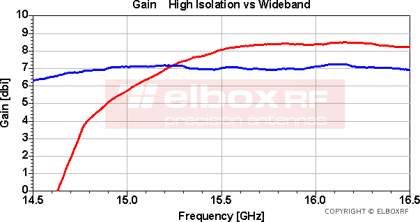
For better understanding differences between the two antennas - TetraAnt 15.5 GHz High Isolation and TetraAnt 15.5 GHz Wideband, the presented below diagrams shows the mutual coupling and the gain of both antennas
- The Wideband antenna is shown in blue
- The High Isolation antenna is shown in red
TetraAnt 15.5 GHz High Isolation - additional information
- Product is covered by a 2-year warranty
- Supported Product - ask the designer: fert(at)elboxrf(dot)com
- Project - 2021. Designer: company owner-Przemyslaw Fert