TetraAnt 5 60 17 HV
2x2 MIMO Sector Antenna, HV Polarizations, 17 dBi Gain
- 17 dBi gain
- 5.0 to 6.1 GHz bandwidth
- No "pattern blooming"
- Electrical Downtilt
- DC_GROUND
- Completely weatherproof - no vented holes
Important Feature:
- Wide bandwidth 5.0 - 6.1 GHz
- High realized gain (all losses including mismatch)
- High Port_to_Port Isolation: > 30 dB
Related Literature
TetraAnt 5 60 17 HV - the antenna gain
The antenna gain was measured in the slant ranges, with a two-antenna method.
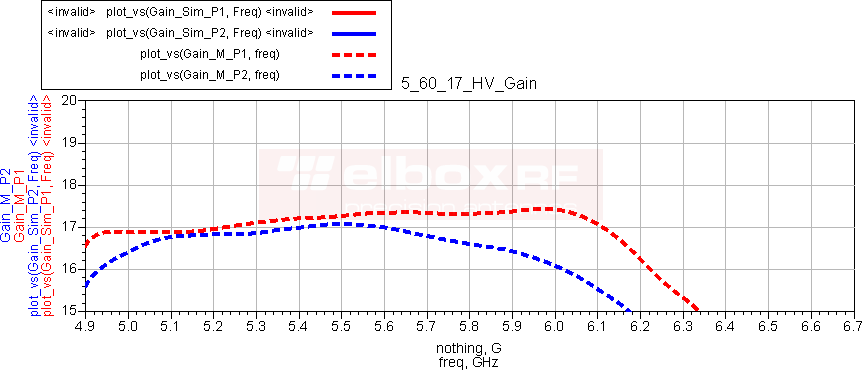
This figure shows the realized gain of the antenna. It takes into account all antenna's losses - it was measured at the connector reference plane.
The Y axis starts at 15 dBi and stops at 20 dBi. The X axis starts at 4.9 GHz and stops at 6.7 GHz with the step of 100 MHz. Gains for the Port1 (Horizontal polarization) and the Port2 (Vertical polarization) are depicted in red and blue, respectively. Please note that the antenna operates over the 5.0 - 6.1 GHz frequency range.
TetraAnt 5 60 17 HV - Port to Port Isolation
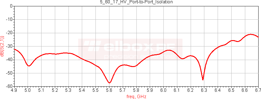
The Port to Port Isolation was measured in the set-up consisted the following components: the Advantest R3860A RF Component analyzer, a set of test coaxial cables, and the simple anechoic chamber.
This kind of measurements are rather straightforward assuming that the instrument and coaxial cables are calibrated and there is no evidence of strong reflection.
One can see the very good isolation between ports or antenna's connectors, better than 35 dB in the 5.0 - 6.1 GHz frequency range
TetraAnt 5 60 17 HV - VSWR
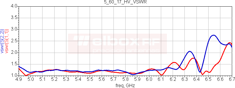
The raw data taken at the Port to Port measurement in the set-up as described above was the source for the following VSWR vs Frequency graph.
Please note the exceptional low VSWR in the whole frequency range 5.0 - 6.1 GHz. It means that the reflection losses are lower than 0.1 dB. You can check it here: Impedance Mismatch Loss
The Red line - Port1, the Blue one - Port2.
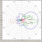
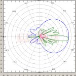
TetraAnt 5 60 17 HV - Directional Patterns in Polar Coordinates - Port P1 (H Polarized)
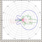
The following are horizontal polarized - Port1 - radiation patterns:
Blue and green are for Azimuth and Elevation planes Co-polar. Red and Pink are for Cross-polar, respectively. The frequency points are: 5.0 - 5.5 - 6.1 GHz. It should be noted a very low level of Cross-polar components.
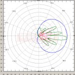
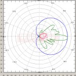
TetraAnt 5 60 17 HV - Directional Patterns in Polar Coordinates - Port P2 (V Polarized)
The following are vertical polarized - Port2 - radiation patterns:
Blue and green are for Azimuth and Elevation planes Co-polar. Red and Pink are for Cross-polar, respectively. The frequency points are: 5.0 - 5.5 - 6.1 GHz. It should be noted a very low level of Cross-polar components.
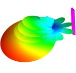
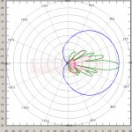
The 3D radiation intensity is useful for checking if any lobe has been omitted in the two-dimensional radiation characteristics.
TetraAnt 5 60 17 HV - Specifications
Electrical Parameters
- Frequency Range: 5.0 - 6.1 GHz
- Polarization: HV Linear
- Peak Gain: 17 dBi
- Impedance: 50 ohm
- VSWR: <= 1.5:1
- Azimuth Beamwidth: 52 - 71 degrees for both polarizations
- Elevation Beamwidth: 7.4 - 9.5 degrees for both polarizations
- Electrical Downtilt: -4 degrees
- Back Radiation: <= -25 dB
- Cross Polar Isolation: >25 dB
- Port to Port Isolation: >30 dB
- Maximum power: 15 W
- Protection against static electricity: DC ground
Mechanical Parameters
- Technology: Microstrip, the 8x1 array
- Connector: N Female on the back, tested to 12 GHz
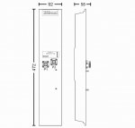
- Dimensions: 475x90x40 mm, with the connector
- Dielectric Radome: White UV resistant PVC
- Base: High strength aluminum alloy
- Construction: Completely weatherproof
- Operating Temperature Range: -30 to +50 C
- Mounting Kit: On the kit, allows elevation adjust. The pipe diameter: 20 – 50 mm
- Antenna Mass: 0.4 kg, Incl. the mounting kit
Additional Information: warranty, the design year, designer
- Product is covered by a 5-year warranty
- Supported Product - ask the designer: fert(at)elboxrf(dot)com
- 2010 Design - designer Przemysław Fert
