Impedance Mismatch Loss
VSWR, Return Loss, Reflected Power Loss
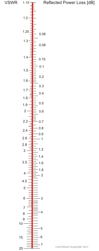
Following scales show the relationship between VSWR and Return Loss [dB]
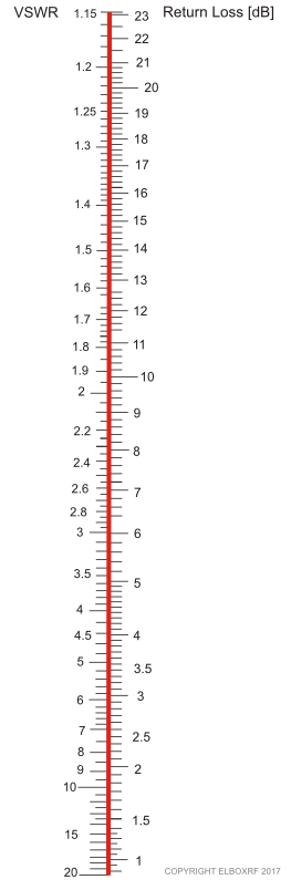
or VSWR and Reflected power Loss [dB]
Example 1 - single polarized panel antenna
Following screenshots are results of the measurement of TetraAnt 2 14 35. It was connected to the analyzer to find out the impedance matching.
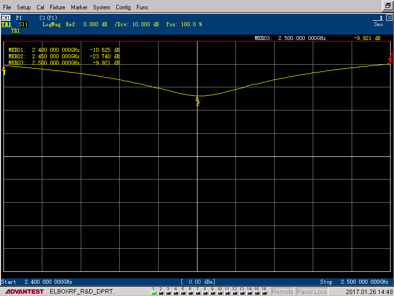
The Return Loss is about:
-10.6 dB at 2.40 GHz
-23.7 dB at 2.45 GHz
-9.9 dB at 2.50 GHz
As we can see, it corresponds to:

- VSWR = 1.83 at 2.40 GHz
- VSWR = 1.14 at 2.45 GHz
- VSWR = 1.94 at 2.50 GHz
From the second relationship - VSWR to Reflected Power Loss, we can find out the losses due to the impedance mismatch:
- 2.40 GHz losses are about 0.45 dB
- 2.45 GHz losses are < 0.01 dB
- 2.50 GHz losses are about 0.5 dB
Example 2 - multi polarized antenna
This is the screen-shot of the VSWR measurement of TetraAnt 5 60 18 XHV. The screen shows 4 simultaneous measurements of the impedance matching for 4 antenna connectors.

The lowest value on the Y - axis represents VSWR=1 that is the best possible value of the VSWR, the ideal impedance matching to the 50 ohm source.
The horizontal red line shows the value VSWR=2.0 In this impedance mismatch the reflected power loss is 0.5dB. Values below 2.0 are widely accepted in the microwave industry as the good impedance matching.