Port to Port isolation
Mutual coupling (port-to-port isolation) between coaxial connectors
- For the antenna equipped with 2 connectors, the port to port isolation measurement is straightforward. It needs only a one measurement session to catch all important Snm parameters: S11 (VSWR at Port1) S22 (VSWR at Port2) and S21 (coupling between Port1 and Port2). In single polarized antennas there is only a one port (coaxial connector), so there is no mutual coupling and no coupling measurement is made.
- Due to the passive device - antenna - the coupling is reciprocal, it means that coupling between Port 1 and Port 2 is the same like coupling between Port 2 and Port 1. Simply S12 = S21
For 3x3 or 4x4 antennas we should make more measurements, because of 3 or 4 Ports, and more possible coupling e.g. (4x4 MIMO)
Port 1 to Port 2 = S21 = S12
Port 1 to Port 3 = S31 = S13
Port 1 to Port 4 = S41 = S14
Port 2 to Port 3 = S32 = S23
Port 2 to Port 4 = S42 = S24
Port 3 to Port 4 = S43 = S34
- As we mentioned earlier, for the passive and reciprocal device (contains only isotropic materials) Snm = Smn. Besides that the antenna is passive device, it can be made of some anisotropic materials like microwave substrate with various dielectric constant along XYZ axes. What is more the joint between the coaxial connector and copper traces (microstrip lines) when is made improperly, can behave like semiconductor joint, generating harmonics at a high incident power, like several watts, e.g. 50 W. But a properly designed and manufactured microstrip antenna is a reciprocal, so Snm = Smn.
- The measurement capability in Elboxrf Lab allow us to make this measurement in one connection DUT (Device Under Test) to the Network Analyzer, that is equipped with 4 independents Test Ports. Of course, we can make four more measurements in this set-up: S11, S22, S33, S44 ( the impedance matching or VSWR). See the picture below - the DUT is the TetraAnt 5 60 18 XHV
Working example: measurements for 4x4 MIMO sector antenna - TetraAnt 5 60 18 XHV
- We are see 4 coaxial connectors: P1, P2 (for H i V polarizations), P3 i P4 (for slant +- 45 deg. polarizations).
- Red lines show possible coupling path: there are 6 unique couplings:
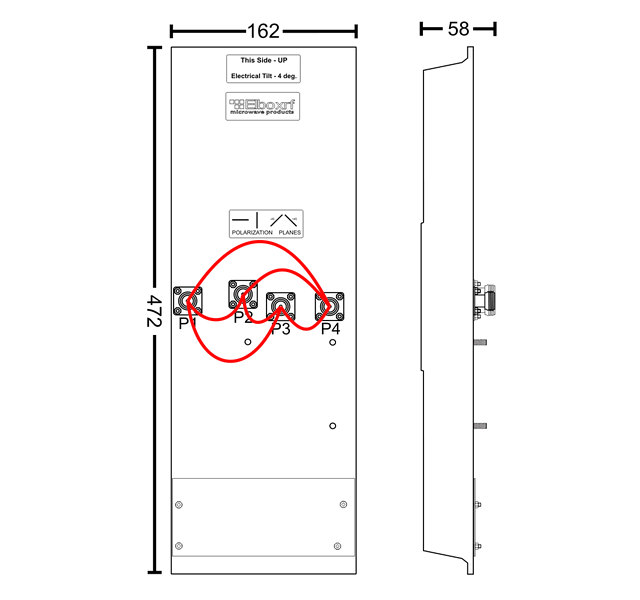
P1 to P2 (S21)
P1 to P3 (S31)
P1 to P3 (S31)
P1 to P4 (S41)
P2 to P3 (S32)
P2 to P3 (S32)
P2 to P4 (S42)
P3 to P4 (S43)
P3 to P4 (S43)
- All measurement were made on the R3860A RF Component Analyzer - pictures show screenshots. As can be seen the one measurement session is enough for taking all important scattering (Snm) parameters.
This was possible because the R3860 has 4 independent measurement ports - in the single sweep we can take all scattering parameters: S11, S22, S33, S44 (the matching) and S21, S31, S41, S32, S42, S43 (the mutual coupling)
- In the similar example we will show the impedance matching measurement in the section: Technology - Matching (VSWR).
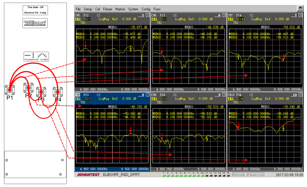
P1 to P2 = S21 better than - 30 dB
P1 to P3 = S31 better than - 45 dB
P1 to P3 = S31 better than - 45 dB
P1 to P4 = S41 better than - 45 dB
P2 to P3 = S34 better than - 45 dB
P2 to P3 = S34 better than - 45 dB
P2 to P4 = S42 better than - 45 dB
P3 to P4 = S43 better than - 30 dB
P3 to P4 = S43 better than - 30 dB
- This screenshot shows the S21 measurement with an explanation. As we can see, the isolation between port 1 and 2 is better that 30 dB. The red line shows -30 dB or 30 dB below the reference.
The thin yellow line is the coupling between connector 1 and connector 2 versus frequency.

Another example: the isolation measurement for 2x2 MIMO antenna - Kathrein X-polarized 65 deg.
- This sector antenna is designed for use in PCS and 3G/UMTS polarization diversity systems and has the following parameters:
Frequency range 1710–2170 MHz
VSWR <1.4:1
Impedance 50 ohms
Intermodulation (2x20w) IM3: <-150 dBc
Polarization +45° and -45°
Connector 2 x 7-16 DIN female
Isolation >30 dB
Maximum input power 150 watts (at 50°C) per input
- As this post is about the isolation, we can check if this parameter follow the specification.
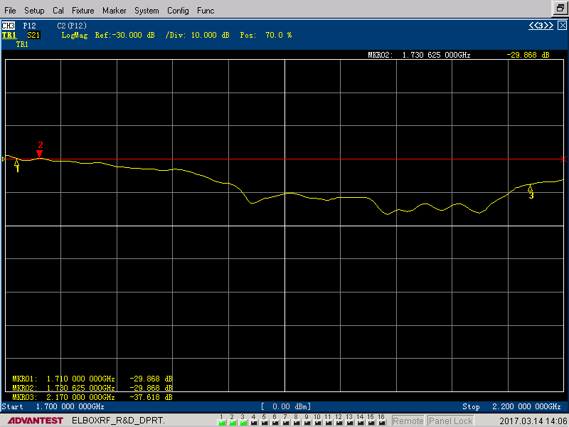
- The above measurement shows that the S21 parameter is on the specs. In the operational band - 1710 to 2170 MHz - isolation is better than 30 dB