Milestones
1995 - active RF tag
-
Elboxrf awarded a contract from The Department of Telecommunications of AGH-UST (University of Science and Technology, Krakow) to design, develop and manufacture the Radio Frequency Identification System.
-
During the work, Elboxrf developed an original system for tracking an active RF tags. The system consisted up to 255 transmitters, microstrip antennas with integrated RF preamplifier, and the five-processor central unit with RF receivers.
-
The system operated on the ISM 433MHz band was successfully tested on the experimental mine "Barbara" in Mikołów under real conditions - in the underground site, with the AGH-UST and Poland's government observers
-
On the test site this sophisticated system was able to count without errors all units attached to the mining crash helmet worn by two groups of miners. The system then inform the operator about number and direction of evacuation of each miner.
-
Below: an active RF Tag and a part of a control unit.
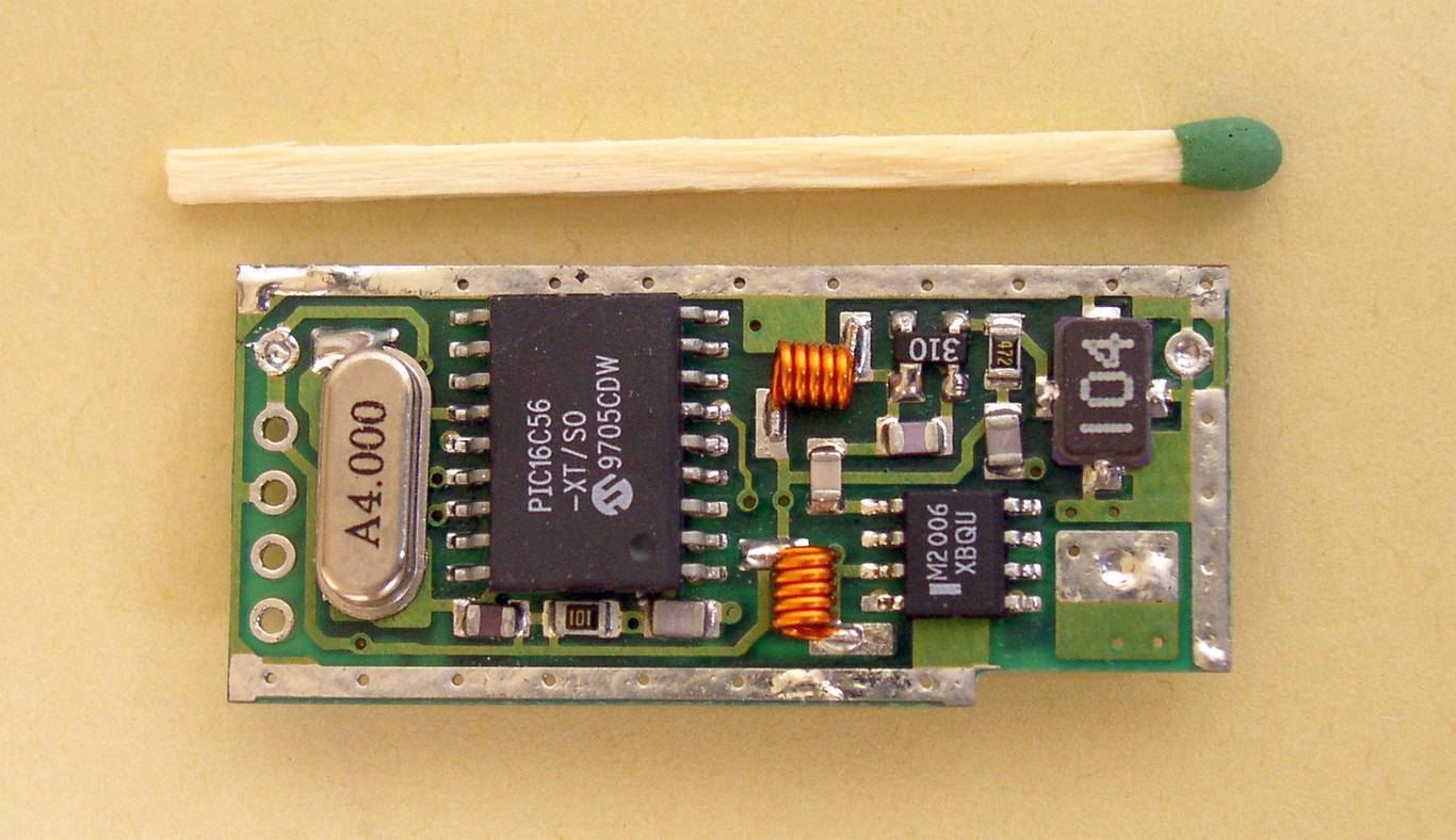
The active RFID tag, microcontroller side
This tiny battery-operated transmitter was designed to have no less than +10 dBm transmit power in the 433 MHz ISM band at DC voltage between 2.5 - 3.5V.
At this side you can see the PIC16C54 uController from MICROCHIP, the MRF2006 IC from HEWLETT-PACKARD and the Surface Acoustic Wave component from RFM.
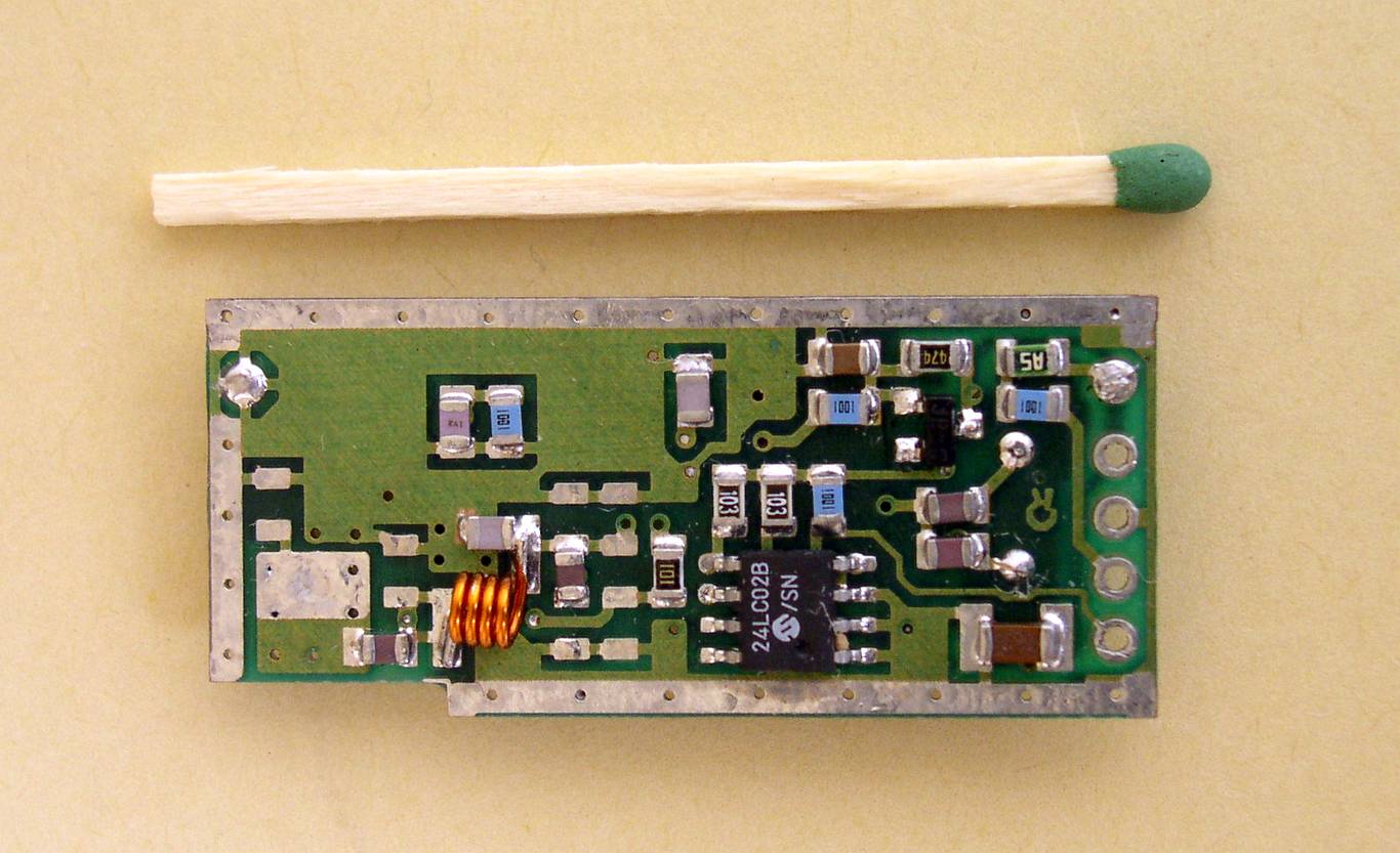
The back side of the active RFID tag
The whole unit was carefully screened and immersed in a epoxy resin. The average Icc was about 2 mA.
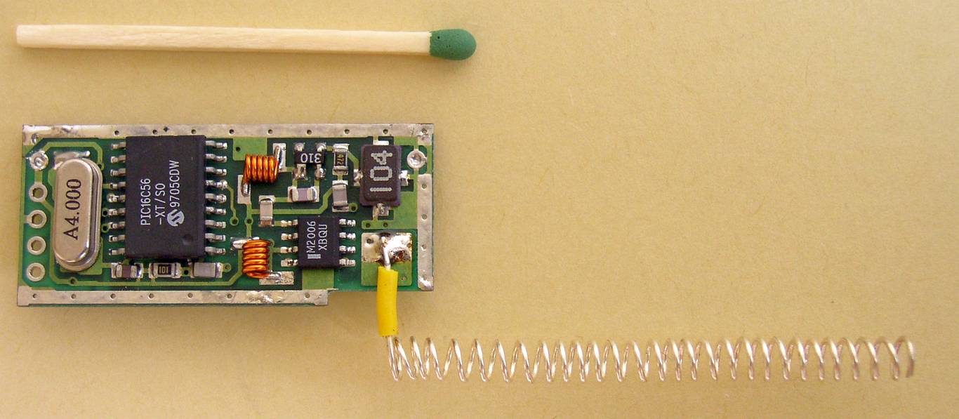
The transmitter with the helical antenna attached
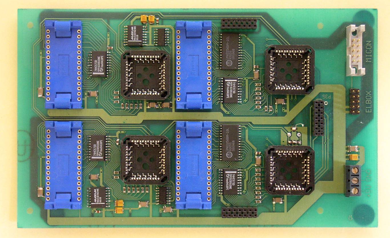
The main CPU unit.
The remaining fifth processor was on the radio board.
MICROCHIP is a registered trademark of Microchip Technology Inc. HEWLETT-PACKARD is a registered trademark of Hewlett-Packard Co., then Agilent Technologies, Inc., now Keysight. RFM is a registered trademark of RF Monolithics, Inc.
1994 - voice scramblers were developed
-
Elboxrf received an order for developing voice-scramblers for upgrading ready-made radiotelephones.
-
After a few month of work we designed the range of programmable voice-scramblers.
-
The most advanced unit was dimension of 43x22x6.5mm. It was in form of two-sided PCB with elements on each side. This scrambler was equipped with a voice codec, modem, EEPROM, DC-stabilizer, uController and the programmable socket.
-
It was a real effort to develop schemes for the coding sequence and for the synchronization algorithm.
-
As a result the voice transmission was undistorted and the very difficult for descramble by unauthorized person. Also synchronization was so fast, that the user does not know when the transmission was switched to coded mode. This work was very important for many next Elboxrf's projects including 433 MHz radio modems, developed in 2000. The data transmission was synchronized immediately, even when the decoded signal was very noisy.
-
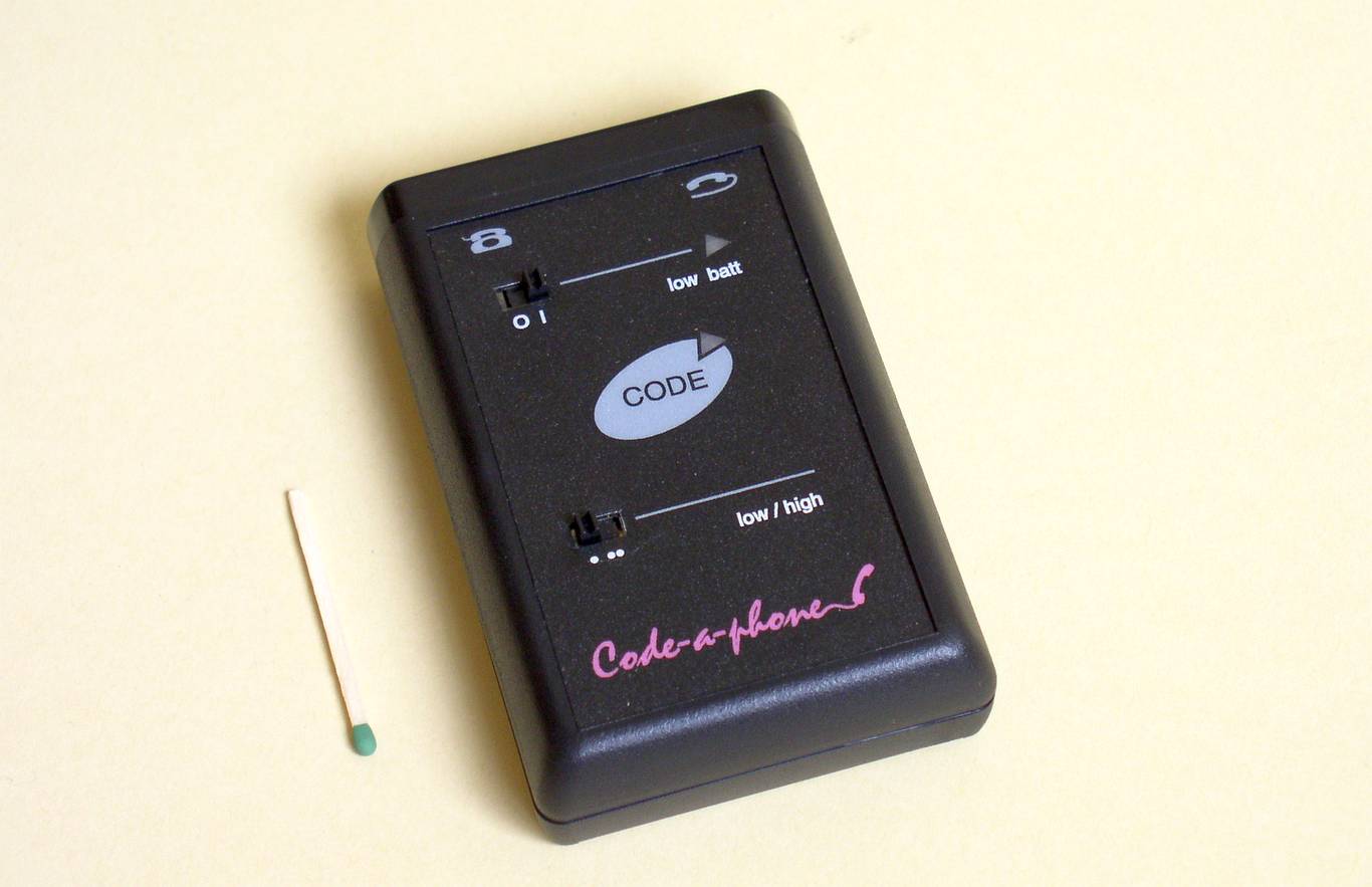
We developed also the CODE-a-PHONE, a full duplex voice-scrambler for telephones.
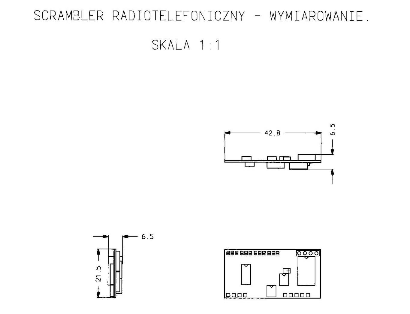
The outline.
As you can see, the whole unit was very compact: 42.8 x 21.5 x 6.5 mm
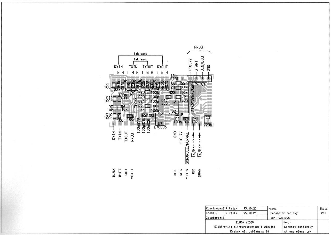
A phantom view showing parts trough the one side of PCB
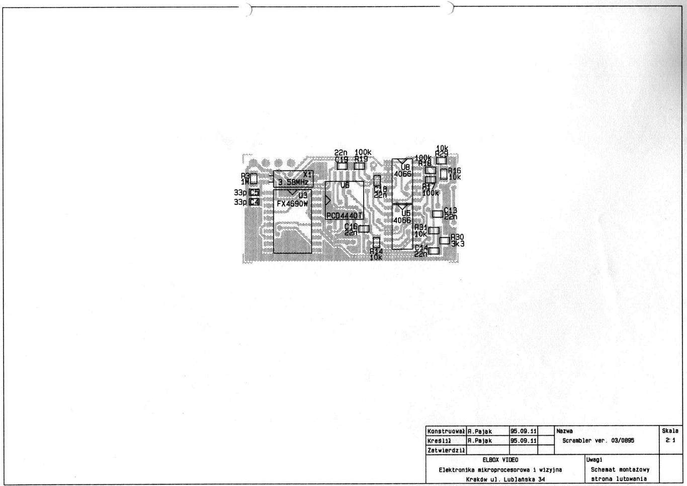
A phantom view showing parts trough the second side of PCB

Schematic diagram of the voice-scrambler
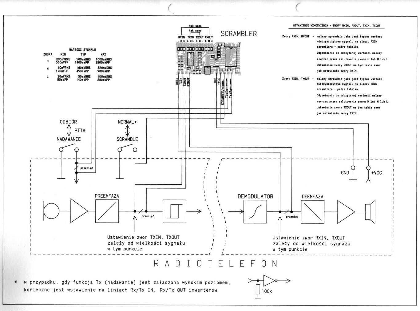
This scrambler was semi-duplex like a most handy radiotelephones
The radiotelephone's button "push-to-talk" was utilized for switching internal circuit in the scrambler.
A full-duplex telephone voice-scrambler.
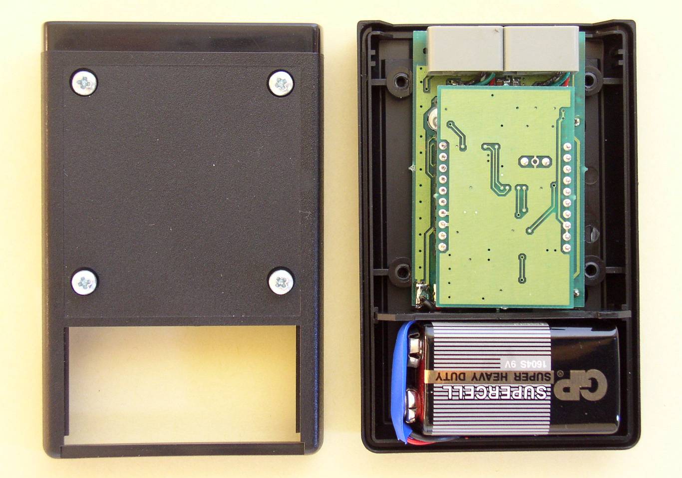
... after removing a bottom cover.
You can see the piggy-back module; the fsk modem and logic.
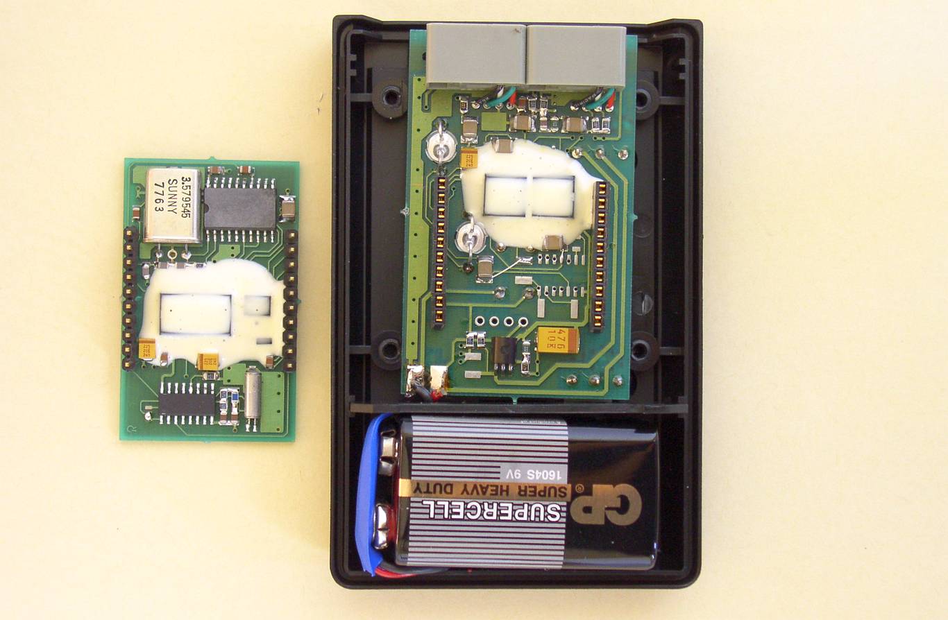
Two modules disconnected.
The covered by a epoxy-resin elements are uController ST6220 from SGS-THOMSON and two integrated scramblers - PCD4440 from PHILIPS.
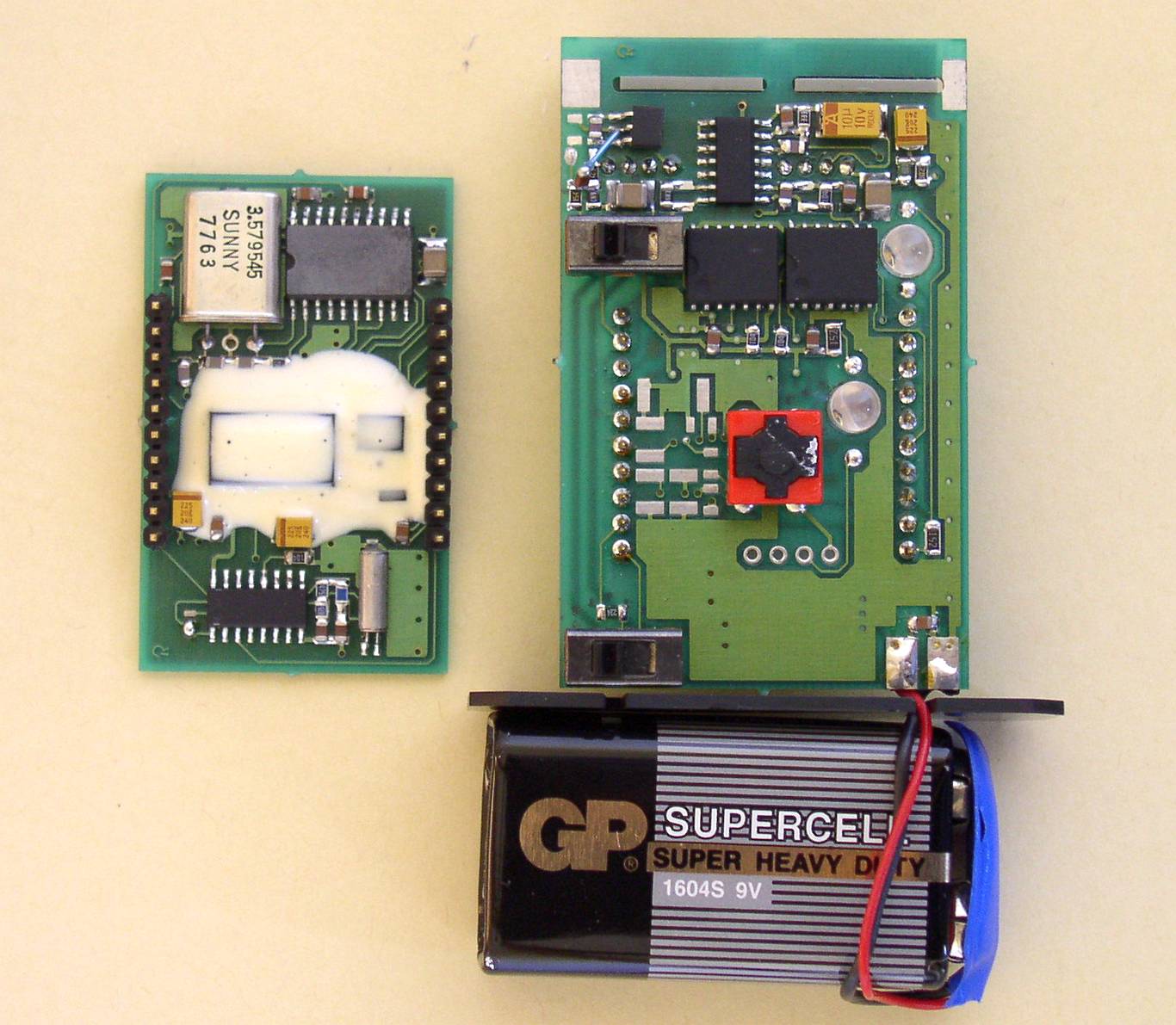
The another view of internal parts of the voice scrambler
The central button is for activate the scrambler at any time during the telephone conversation. At the right are LED's.
SGS-THOMSON is a registered trademark of SGS-Thomson Microelectronics; now STMicroelectronics. PHILIPS is a registered trademark of Royal Philips Electronics N.V.
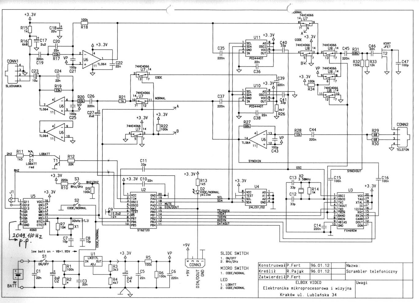
The schematic diagram of the full duplex telephone voice scrambler
SGS-THOMSON is a registered trademark of SGS-Thomson Microelectronics; now STMicroelectronics. PHILIPS is a registered trademark of Royal Philips Electronics N.V.
1993, May - Elbox received a found from The State Committee for Scientific Research for his Local Paging System.
- Under the contract - No. 0575/C.S5-8/93 - Elboxrf developed the small PC-operated control unit, a low-power RF amplifier and the numeric one-way pager receiver. All the work were finished by the April 1994.
1993 - PAGER receiver
-
After two years of preparing, we developed some of prototypes of pager receiver.
-
We evaluated various types of RF receiver - heterodyne system, offset IF and ZERO IF systems, antennas - loop antenna, printed loop antenna, ferrite antenna with one-turn high-Q coil, and various display systems.
-
All pagers were designed for the band 160 MHz.
-
In 1999 we have developed the advanced alphanumeric pager for a wide area paging system

Superheterodyne receiver with two IF frequencies.
The first IF is about 21 MHz and the second IF is the standard 455 kHz. (This filter is removed). This receiver based on the MC3367 integrated circuit from MOTOROLA.

The pager receiver
An antenna, an RF preamplifier and a DC-switch for an IC.
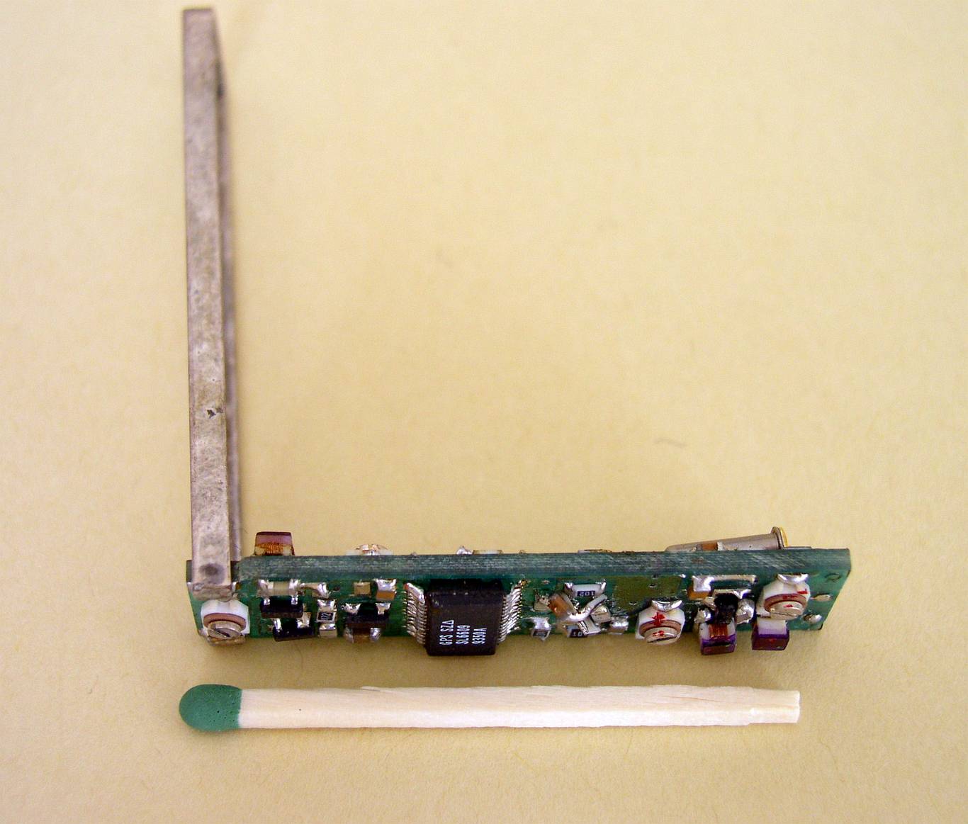
Other conception of an RF unit - ZERO - IF
Due to the self reception, the antenna is as far as possible from the local oscillator. This receiver based on the SL6609 direct conversion FSK data receiver from GEC PLESSEY
A front view ZERO IF PAGER receiver
An RF preamp., an IC and the local oscillator.
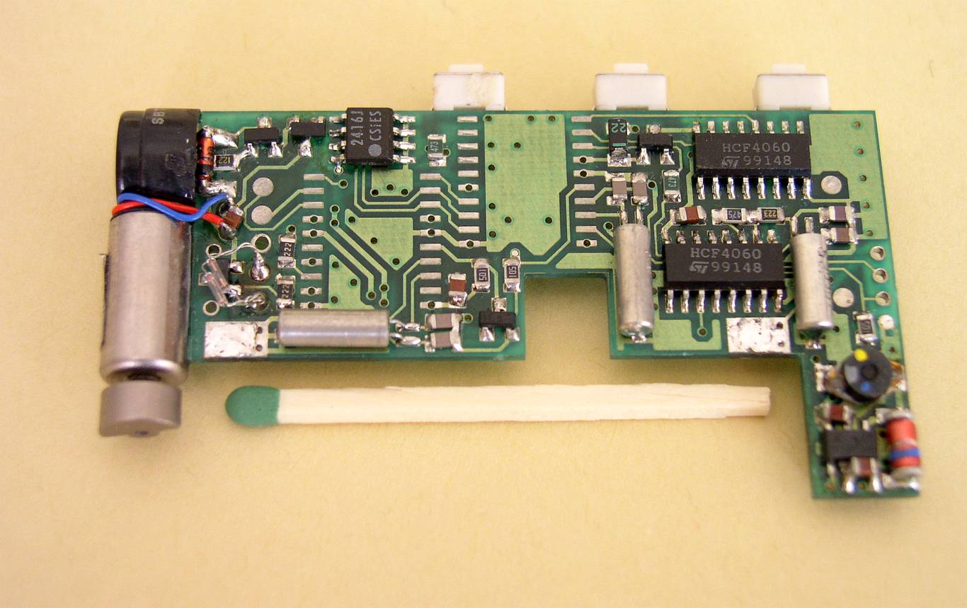
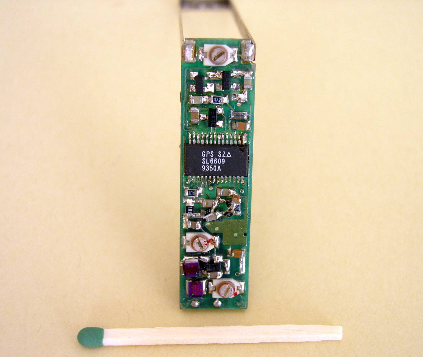
Control unit with two uC on the PCB
As far as I remember it, the first was for acquiring & decoding, the second one for other logic - buttons, an vibrating motor, a buzzer and a micro incandescent lamp. In this particular PCB uControllers are removed. At the bottom right is a DC-DC converter. This project was beep only pager - the Beeper. We implemented the ST6220 microcontrollers from SGS-THOMSON.
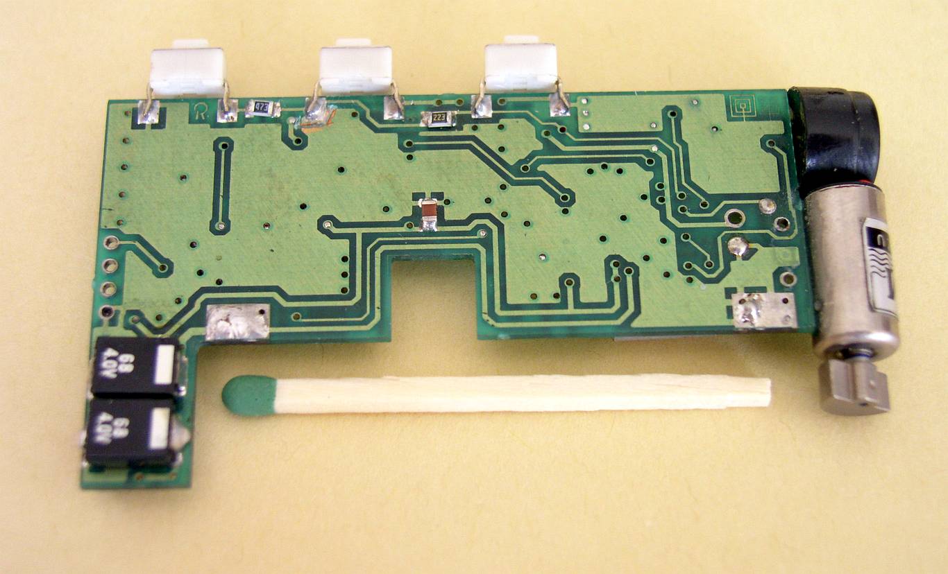
Remaining components of the pager receiver
on the left you see two large capacitors mounted underneath the DC-DC converter. this was the only way to suppress the noise from this converter. The RF part - on the separate board, was mounted at this side. This PCB side was designed to have a large ground area; remaining tracks are DC-only.
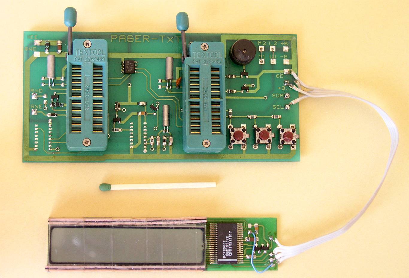
Designed in Elbox the evaluation board for PCF8866 IC LCD controller and a LCD itself.
The above PCB is a evaluation board for alphanumeric/beep pager. The one 7-segment from 8 characters LCD mimics an letter. The PCF8866 come from PHILIPS.
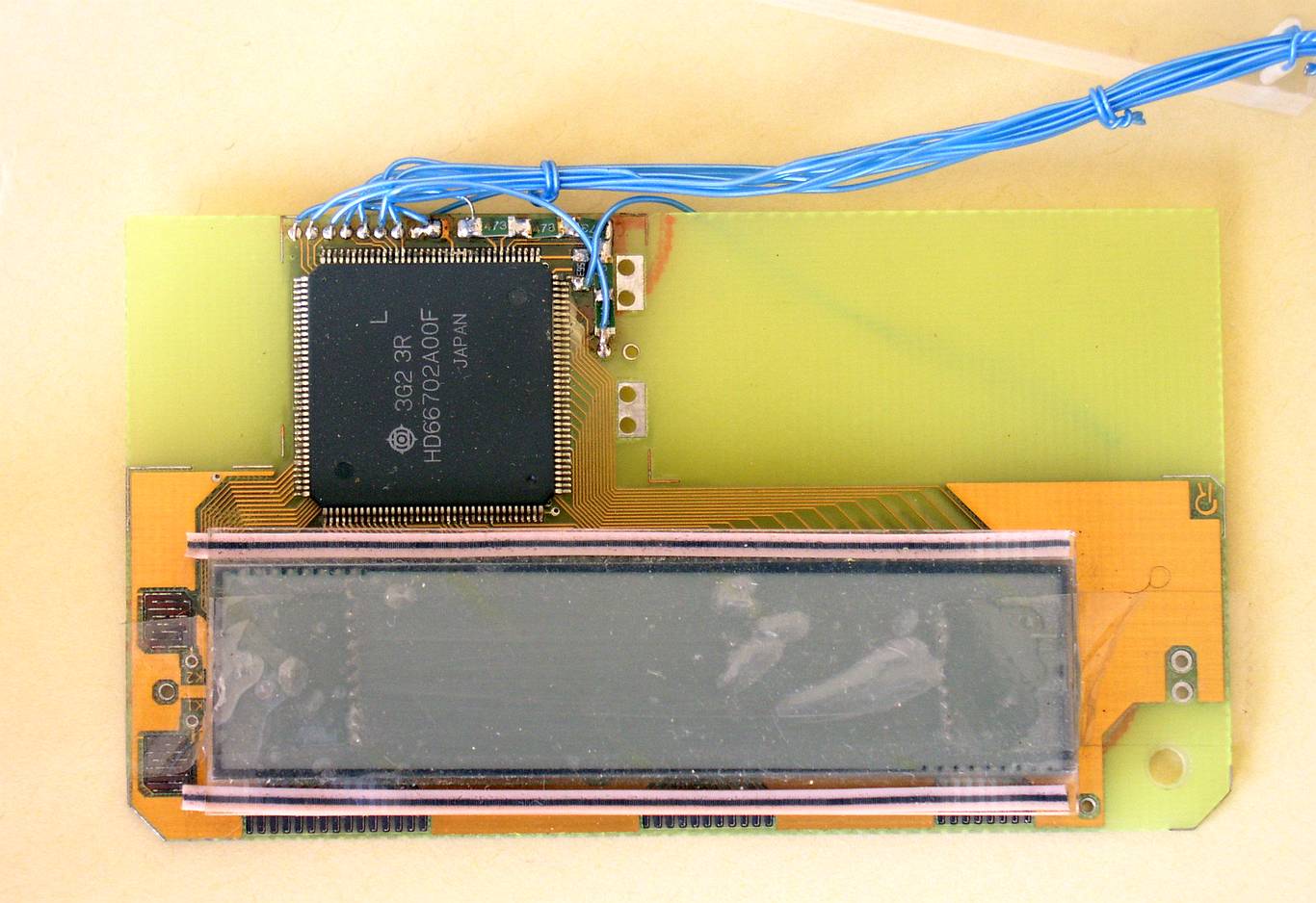
Completed LC display and an controller - HD66702 from Hitachi.
It was probably the first ever commercial available 5x7 and 5x10 dot matrix liquid crystal display controller and driver - January 1992. We received a sample from Japan. It was assembled by hand.
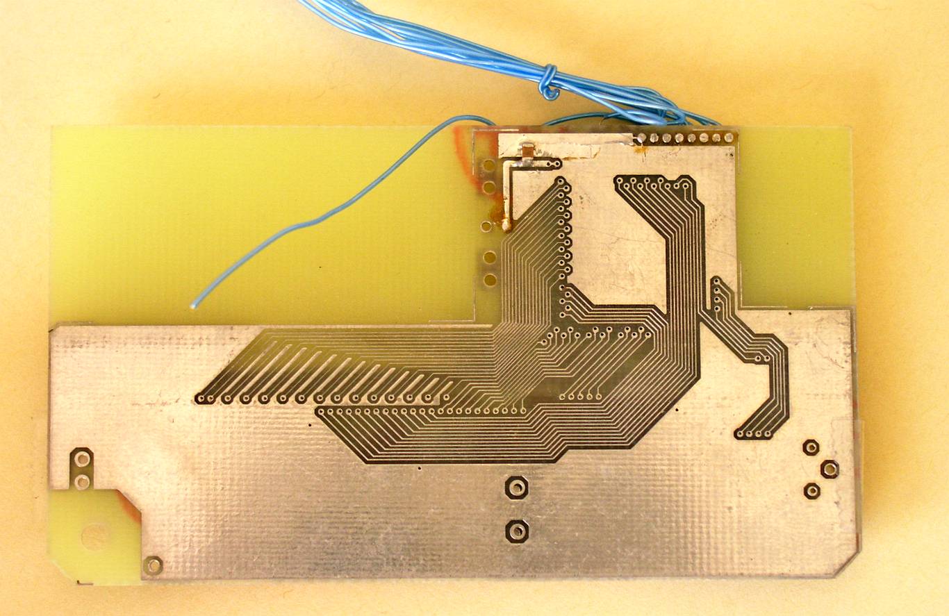
Completed LCD and the controller. A bottom side.
The bottom side of the liquid crystal display
PHILIPS is a registered trademark of Royal Philips Electronics N.V.
HITACHI is a registered trademark of Hitachi, Ltd.
1989 - The ultrasonic movement detector
-
This sensor was designed for a small residential security systems
-
Because of lack of the right housing, the injection molded form was designed under original Elbox's cover project
-
The housing was made of the polycarbonate
-
Most of this sensors, produced in the years 1990-1994 are still working. (Data taken at the time of writing of this original version of the post - 2003)

The ultrasonic burglar sensor
Ultrasonic Movement Detector - a black part is the cover foam. Because it should be transparent for ultrasonic waves it took some time to find the proper material.
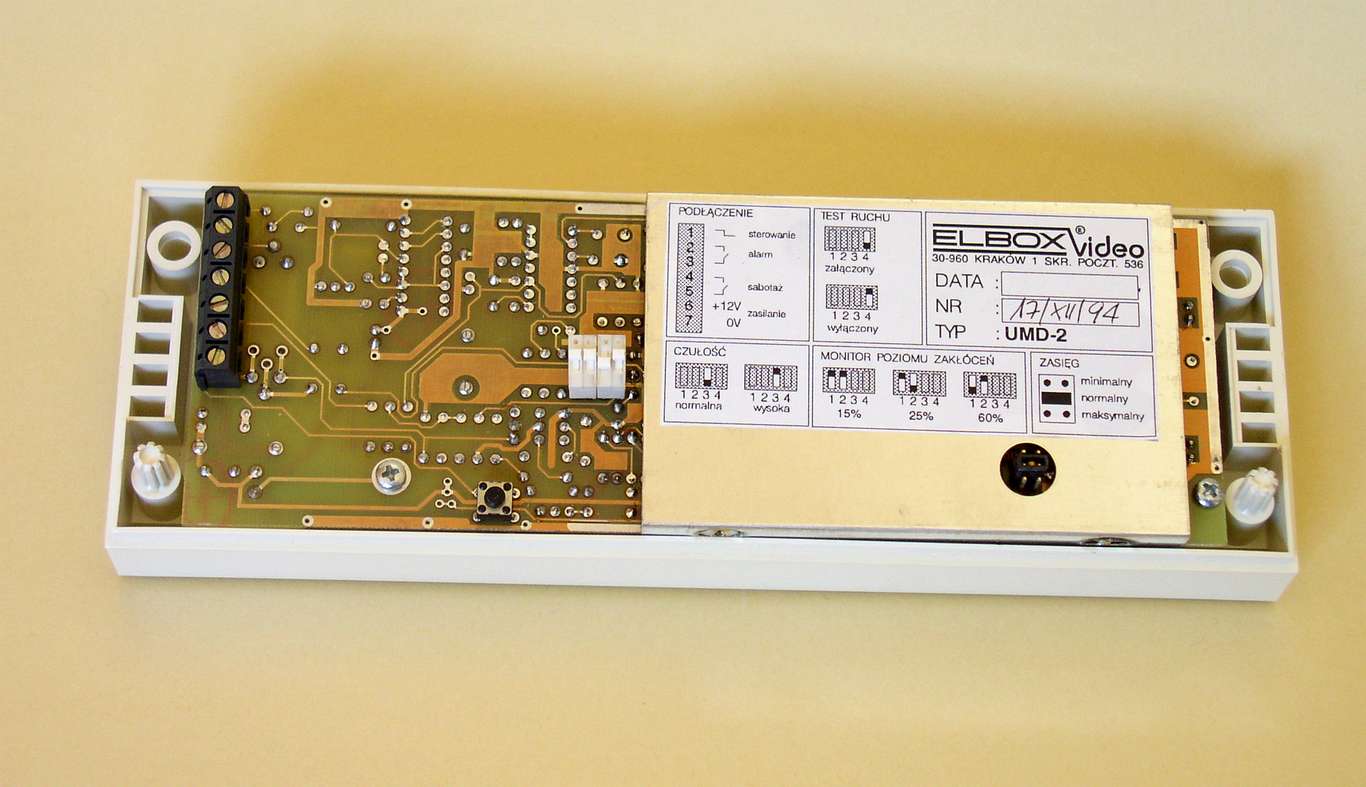
The inside view of this detector.
The version on a picture is equipped with some useful functions: movement test, sensitivity and a range switch and a interference level monitor with a memory.
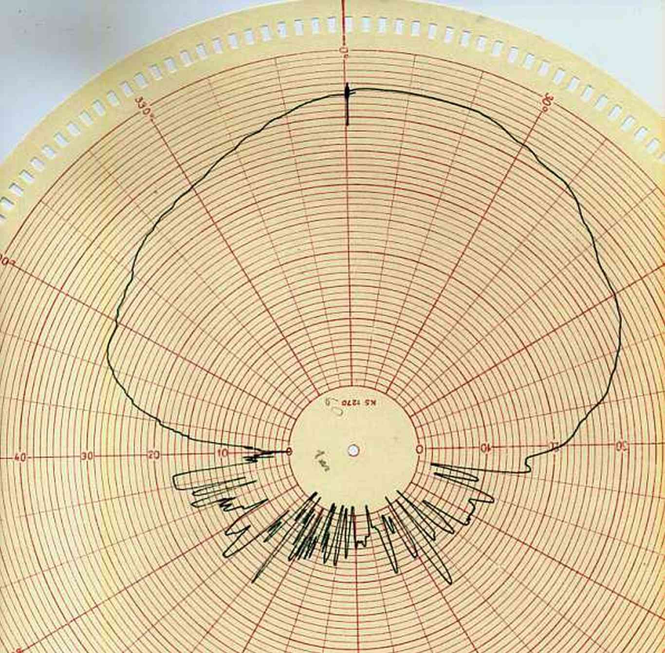
This sensor was well characterized
Here, the ultrasonic radiation pattern.
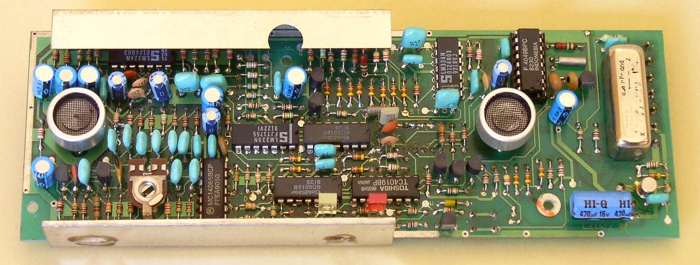
An element side of the PCB.
Two transducers, two LED's and other elements.
1985 - June - the SECAM coder for ZX SPECTRUM was introduced
-
It was a small, simple unit designed for upgrading the famous SINCLAIR ZX SPECTRUM and SPECTRUM+ personal computers
-
Originally ZX SPECTRUM, was equipped with the PAL coder, so the picture on the SECAM TV sets was black and white
-
After upgrading, ZX SPECTRUM fans were delighted to see the color picture
-
Because of an tremendous success of VHS system, Elbox designed and started to deliver PAL decoders for SECAM system CTV-sets. By the end of the year we designed PAL decoders for more than eight models of colour TV receivers
-
Among them was the most popular of that time RUBIN 704
Circuit diagram of a coder for the Sinclair's ZX SPECTRUM/SPECTRUM+ personal computers
(Sinclair ZX SPECTRUM and Sinclair ZX SPECTRUM+ are registered trademarks of AMSTRAD Plc.)
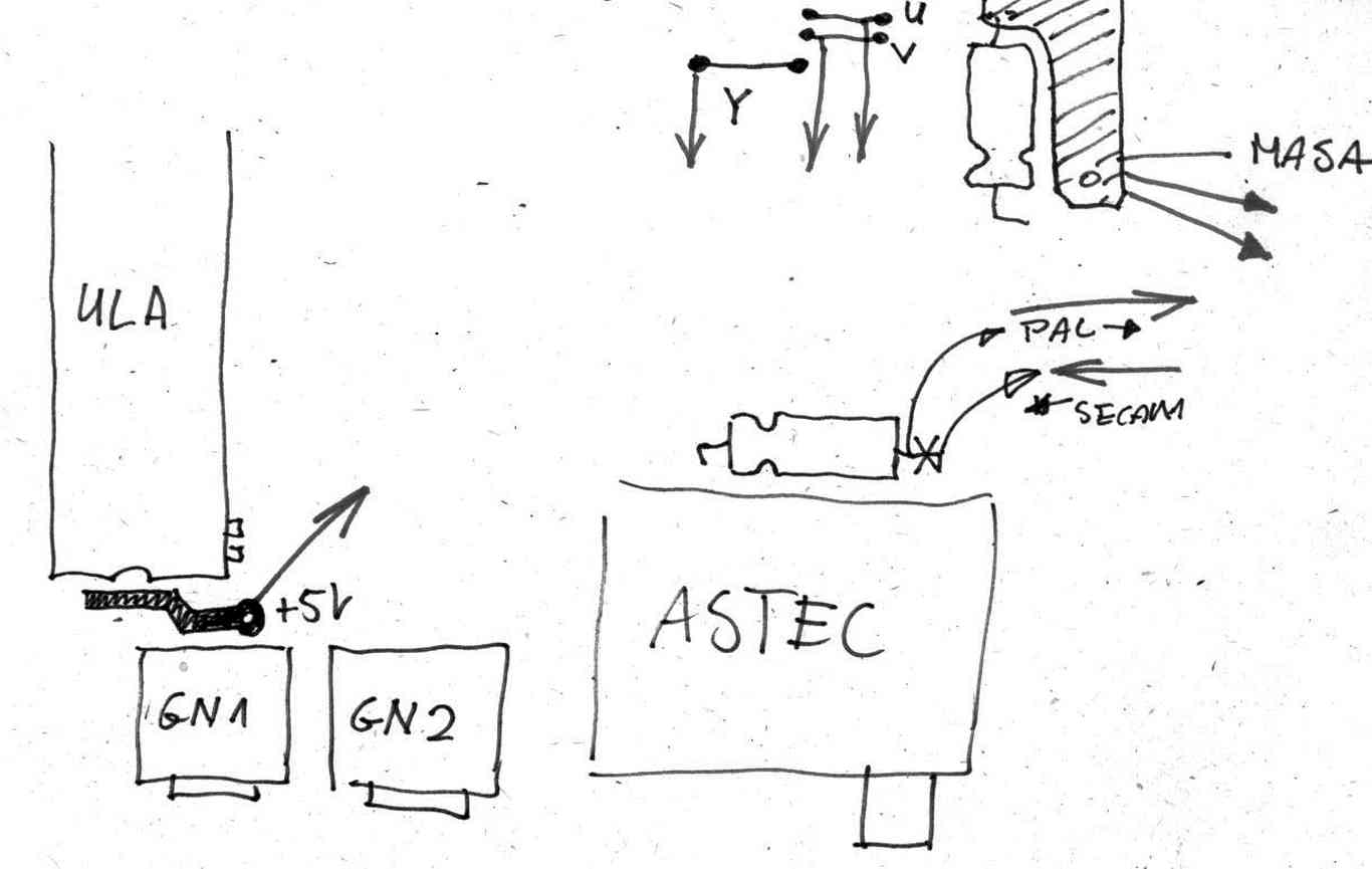
This sketch shows how the SECAM coder was connected to the ZX SPECTRUM's PCB
1984 - Microbox SG signal generator
-
The MICROBOX SG was introduced - SECAM, PAL and NTSC signal generator.
-
Subcarriers were stabilized by the switching Phase-Locked Loop (PLL) unit, coupled to the crystal (Xtal) oscillator , so colour bars on the TV-screen had always the right and within the specification colours. Subcarrier frequencies were temperature and aging independent.
-
By the end of the year it was equipped with a PAL / NTSC coder and other logic circuitry for generating the full Bruch Sequence (from Walter Bruch, a German electrical engineer) - a 4-field blanking sequence generated in PAL coders to ensure that burst phase is the same at the end of each vertical interval.
-
The Bruch Sequence was important feature for the PAL TV system
-
And finally the VHF/UHF modulator was designed - the whole unit was lightweight and measured 24x11x5cm.

The Schematic diagram - the PAL/NTSC 4.43 MHz coder

The full Bruch sequence
Before the Computer-Aided Design (CAD) era becomes popular, the first step to design the logic circuit, was to draw a logic waveform. Here is the 4 TV field Bruch sequence timing chart in its entirety.
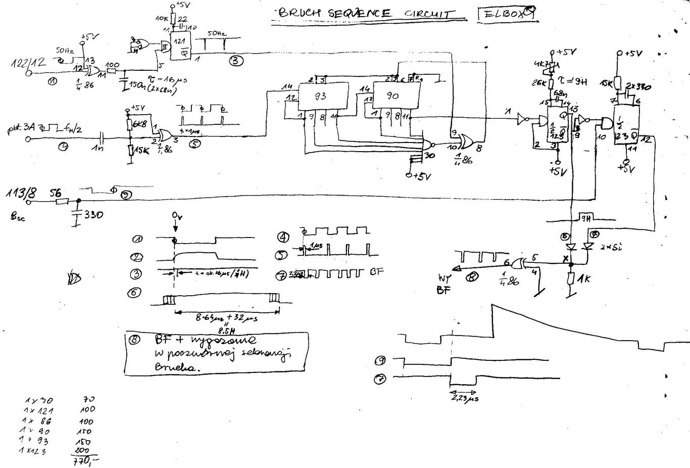
Circuit diagram of a Bruch Sequence generator.
This was a part of the digital section of MICROBOX SIGNAL GENERATOR (SG). This simple circuit is generating the above waveform. On the bottom left-hand corner is the list of used elements and their prices in PLN (1984). TTL elements was 7430, 74121, 7486, 7490, 7493 and 74123

The linearity characteristics of the VCO
Red lines are the SECAM subcarriers mask.
The longer line is the ideal characteristic of an VCO. The slightly curved line is the real f/v characteristic of the VCO.
The vertical line is in kHz (3400 to 5200), the horizontal one is in V (1.5 to 3.5)
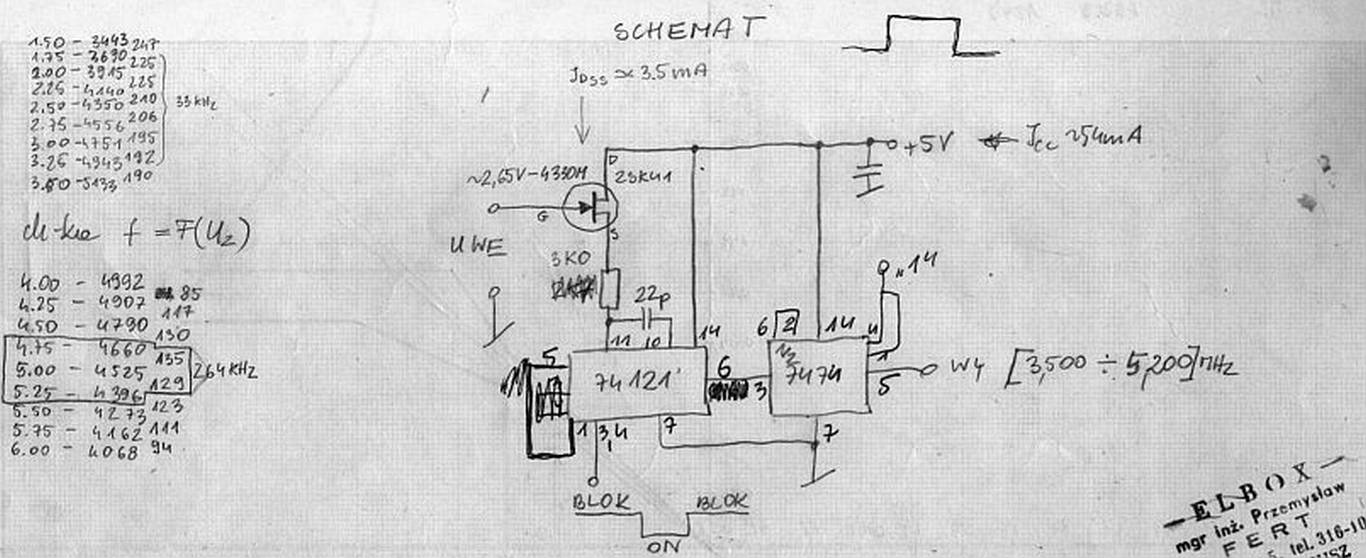
The subcarrier VCO generator
A highly linear VCO was important to generate a high quality subcarriers in the SECAM coder.
After some experiments we found that the above circuit was simple and had a linear f/v characteristic.
But the DC-current was... 54 mA at 5V !
1982 - Elbox was founded
- After few month of work the prototype of the SECAM signal generator was designed. This early version had only a baseband SECAM output, and a very simple VHF modulator tuned to the one RF-TV channel.
- Colour subcarriers were unstabilized.

The block diagram of the SECAM Test Signal Generator
Numbers in small circles correspond to waveforms.
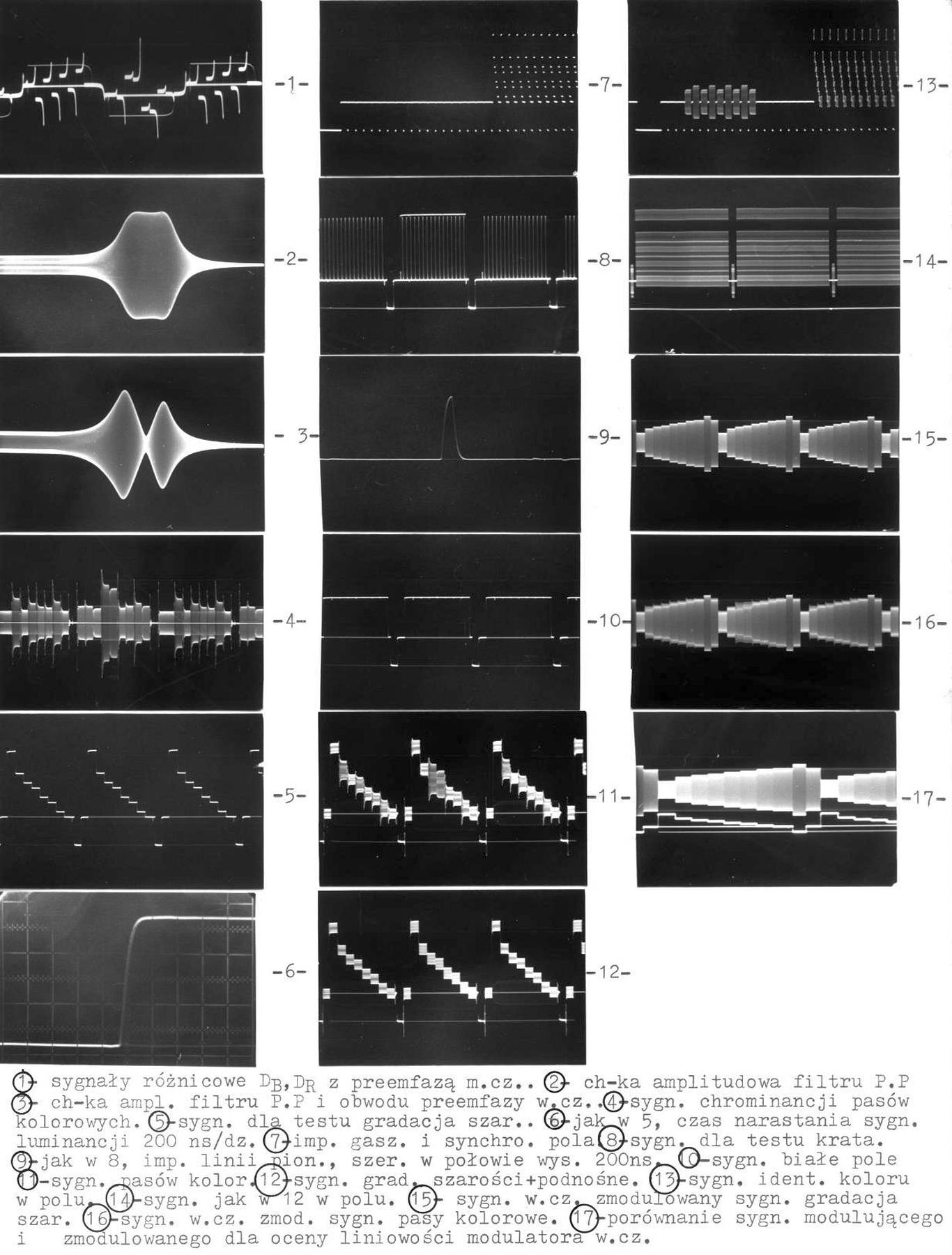
Oscilloscopes waveforms in various points of the signal generator
All of them are photographs taken from the original MICROBOX (the name of this generator) user manual.
Despite of that descriptions are in Polish, some of you will recognize this waveforms.

Chrominance scopes waveforms
Oscilloscopes waveforms of colour subcarriers and the luminance.
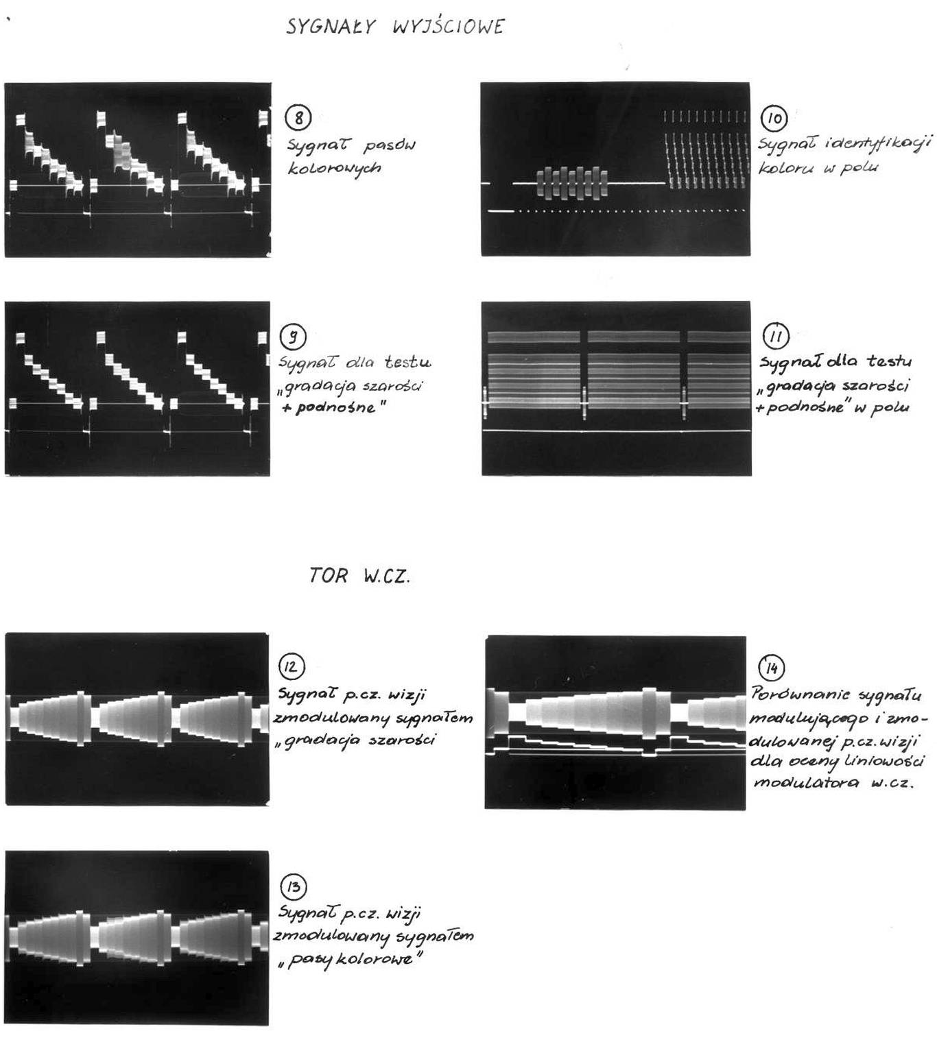
Oscilloscopes waveforms on the outputs: baseband and h.f.