TetraAnt 2 19 20 RSLL
Directional Panel Antenna with Low SLL, 19 dBi, 2.4 GHz
- 18.5 dBi gain
- 2.40 - 2.50 GHz frequency range
- Low SLL
- 30 dB Cross-polar rejection
- 25 dB Front-to_Back ratio
- Protected against static electricity
- Completely weatherproof - no vented holes
In this outstanding antenna we have redesigned the array of radiating elements in such way that antenna is highly immune for signals come from distant stations, outside of the mainbeam direction. This is because all noises and interfering signals are not collected by highly suppressed sidelobes of this unique antenna.
TetraAnt 2 19 20 RSLL delivers a very strong and clean (high S/N) microwave power even in the most interfering environment. Is is especially sufficient in the dense urban area with a lot of microwave networks. Because the pattern of antenna is the same for transmit and receive mode, it also do not interfere with other networks.
The unit price. The Minimum Order Quantity (MOQ) is 10 units.
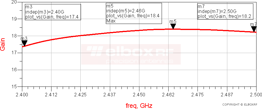
TetraAnt 2 19 20 RSLL - Gain
This figure shows the realized gain of the antenna. It takes into account all antenna's losses - is measured at the connector reference plane.
The antenna gain was measured in the slant ranges, with a two-antenna method.
TetraAnt 2 19 20 RSLL - VSWR
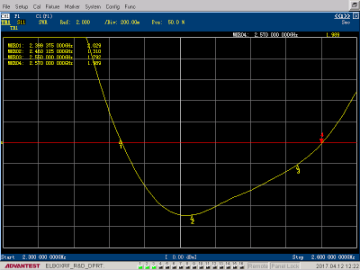
The impedance matching for TetraAnt 2 19 20 RSLL microstrip WiFi antenna is better than 2.0 in bandwidth from 2.40 to 2.57 GHz.
Because the min. lower frequency and the max. upper frequency in 2.4 GHz Wi-Fi frequencies allowed by the FCC are 2.401 and 2.495 GHz, it's clearly visible that this antenna covers the entire Wi-Fi band.
TetraAnt 2 19 20 RSLL - Radiation Patterns
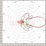
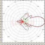
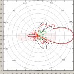
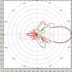
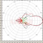
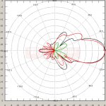
Patterns are referenced to 0 dB, the full scale is 40 dB. Frequencies are: 2.4 - 2.45 - 2.47 - 2.48 - 2.49 - 2.5 GHz. For all frequencies x- (or cross-) polar pattern for E plane, marked in BLUE is out of the scale, because it is lower than -40 dB.
- E vector plane: RED (is parallel to the "waves" symbol on the antenna's cover)
- E vector plane, cross-polar: BLUE
- H vector plane: BLACK (is perpendicular to the "waves" symbol on the antenna's cover)
- H vector plane, cross-polar: GREEN
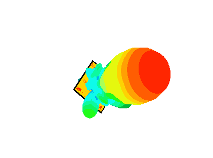
TetraAnt 2 19 20 RSLL - 3D animation of the radiation pattern
Antenna patterns are usually shown in XY or pole coordinates, but this is not enough for fully understanding the radiation pattern of a given antenna. For example, some side lobes can be evident in other cuts like + - 45 degrees planes.
Fortunately we can see also 3D radiation patterns like this one taken at 2.45 GHz for TetraAnt 2 19 20 RSLL. As we can see, there are no evidence of the high level sidelobes at other cuts than that indicated above in XY coordinates.
The direction of the maximum radiation is marked by the "hot" red colour. The simulation frequency was 2.45 GHz.
TetraAnt 2 19 20 RSLL - Specification
Electrical Parameters
- Frequency Range: 2.4 - 2.5 GHz
- Peak Gain: = 18.5 dBi
- Impedance: 50 ohm
- VSWR: <= 2:1
- HPBW plane E (electric): 21°
- HPBW plane H (magnetic): 21°
- Back Radiation: <= -25 dB. See Characteristics
- Cross-Polar Rejection: >30 dB. See Characteristics
- Maximum power: 15 W
- Protection against static electricity: yes - DC ground
Mechanical Parameters
- Technology: Microstrip, the 4x4 array of patches
- Connector: N Female on the back, tested to 12 GHz
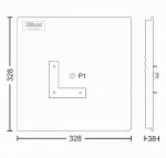
- Dimensions: 330 x 330 x 35 mm, with the connector
- Dielectric Radome: White UV resistant PVC
- Base: High strength aluminum alloy
- Construction: Completely weatherproof
- Operating Temperature Range: -30 to +50 C
- Mounting Kit: On the kit, allows elevation adjust. The pipe diameter: 20 – 50 mm
- Antenna Mass: 1.1 kg, Incl. the mounting kit
Additional Information
- Product is covered by a 5-year warranty
- Supported Product - ask the designer: fert(at)elboxrf(dot)com
- 2004 and 2009 Design - designer Przemysław Fert
